
选择Sokolov的Tiny Renderer教程开始入门。
Sokolov从一个最简单的画点函数开始,一个小节一个小节地讲解怎么画出一条线,怎么填充一个面,怎么逐步加入背面剔除、深度测试、透视相机、着色器等高级功能。每个小节的课程都有详细的讲解以及完整的实现代码可供参考。这个教程一共有9个小节,只要学到第6个小节我们就已经可以实现一个具有可编程渲染管线的软件渲染器了,而这时候的总代码量只有500行而已,可以说是非常简洁适合入门了。
本文只记录在学习过程中遇到的一些问题,和自己的一些想法
Lesson 1 Bresenham’s Line Drawing Algorithm
Second attempt中
void line(int x0, int y0, int x1, int y1, TGAImage &image, TGAColor color) {
    for (int x=x0; x<=x1; x++) {
        float t = (x-x0)/(float)(x1-x0);
        int y = y0*(1.-t) + y1*t;
        image.set(x, y, color);
    }
}
它默认从x0到x1递增画线,而没有考虑到x0和x1的大小。如果x0>x1,此函数就没有作用。
从Fourth attempt continued 到 fifth and final attempt的优化中
Fourth attempt continued
void line(int x0, int y0, int x1, int y1, TGAImage &image, TGAColor color) {
    bool steep = false;
    if (std::abs(x0-x1)<std::abs(y0-y1)) {
        std::swap(x0, y0);
        std::swap(x1, y1);
        steep = true;
    }
    if (x0>x1) {
        std::swap(x0, x1);
        std::swap(y0, y1);
    }
    int dx = x1-x0;
    int dy = y1-y0;
    float derror = std::abs(dy/float(dx));
    float error = 0;
    int y = y0;
    for (int x=x0; x<=x1; x++) {
        if (steep) {
            image.set(y, x, color);
        } else {
            image.set(x, y, color);
        }
        error += derror;
        if (error>.5) {
            y += (y1>y0?1:-1);
            error -= 1.;
        }
    }
}
fifth and final attempt
void line(int x0, int y0, int x1, int y1, TGAImage &image, TGAColor color) {
    bool steep = false;
    if (std::abs(x0-x1)<std::abs(y0-y1)) {
        std::swap(x0, y0);
        std::swap(x1, y1);
        steep = true;
    }
    if (x0>x1) {
        std::swap(x0, x1);
        std::swap(y0, y1);
    }
    int dx = x1-x0;
    int dy = y1-y0;
    int derror2 = std::abs(dy)*2;
    int error2 = 0;
    int y = y0;
    for (int x=x0; x<=x1; x++) {
        if (steep) {
            image.set(y, x, color);
        } else {
            image.set(x, y, color);
        }
        error2 += derror2;
        if (error2 > dx) {
            y += (y1>y0?1:-1);
            error2 -= dx*2;
        }
    }
}
这个过程去掉了浮点数的运算,在Fourth attempt 中,我们可以发现 derror和error只是起到的比较大小的作用,对于y的值没有影响。所以我们可以将derror乘上一个值 2dx 消去浮点数。至于为什么要乘 2dx,
- derror中有 /dx,所以×dx消去了derror中的浮点。
- error和0.5比较,所以x2 消去了浮点比较。
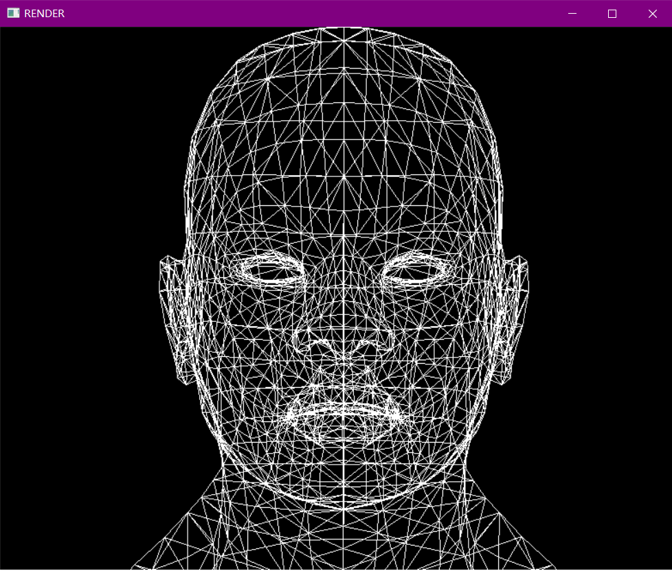
Wireframe rendering
在当前版本的代码中并没有model->face(i); 这一函数。我们可以在model类中加入下面一行实现。
std::vector<int> face(int i) { return std::vector<int>(facet_vrt_.begin() + i*3, facet_vrt_.begin() + i*3 + 3); }
阅读源码可知 facet_vrt_ 变量里面存储的是三角形的顶点坐标的索引,也就是我们需要画的线的端点的索引。
然后 Vec3f 改成 vec3。
最终
Model *model = new Model("obj\\african_head\\african_head.obj");
for (int i = 0; i < model->nfaces(); i++) {
    std::vector<int> face = model->face(i);
    for (int j = 0; j < 3; j++) {
        vec3 v0 = model->vert(face[j]);
        vec3 v1 = model->vert(face[(j + 1) % 3]);
        int x0 = (v0.x + 1.) * width / 2.;
        int y0 = (v0.y + 1.) * height / 2.;
        int x1 = (v1.x + 1.) * width / 2.;
        int y1 = (v1.y + 1.) * height / 2.;
        line(x0, y0, x1, y1, image, white);
    }
}
实现效果
Lesson 2 Triangle rasterization and back face culling
这一节介绍了填充三角形的两种基本方法。
Old-school method: Line sweeping 即通过一条条的线段绘制成图形
这种是原始的,我们自己能想到的代码,缺点是对多线程的支持较差。
The method I adopt for my code
Vec3f barycentric(Vec2i *pts, Vec2i P) {
    Vec3f u = cross(Vec3f(pts[2][0]-pts[0][0], pts[1][0]-pts[0][0], pts[0][0]-P[0]), Vec3f(pts[2][1]-pts[0][1], pts[1][1]-pts[0][1], pts[0][1]-P[1]));
    /* `pts` and `P` has integer value as coordinates
    so `abs(u[2])` < 1 means `u[2]` is 0, that means
    triangle is degenerate, in this case return something with negative coordinates */
    if (std::abs(u[2])<1) return Vec3f(-1,1,1);
    return Vec3f(1.f-(u.x+u.y)/u.z, u.y/u.z, u.x/u.z);
}

void triangle(Vec2i *pts, TGAImage &image, TGAColor color) {
    Vec2i bboxmin(image.get_width()-1,  image.get_height()-1);
    Vec2i bboxmax(0, 0);
    Vec2i clamp(image.get_width()-1, image.get_height()-1);
    for (int i=0; i<3; i++) {
        for (int j=0; j<2; j++) {
            bboxmin[j] = std::max(0,        std::min(bboxmin[j], pts[i][j]));
            bboxmax[j] = std::min(clamp[j], std::max(bboxmax[j], pts[i][j]));
        }
    }
    Vec2i P;
    for (P.x=bboxmin.x; P.x<=bboxmax.x; P.x++) {
        for (P.y=bboxmin.y; P.y<=bboxmax.y; P.y++) {
            Vec3f bc_screen  = barycentric(pts, P);
            if (bc_screen.x<0 || bc_screen.y<0 || bc_screen.z<0) continue;
            image.set(P.x, P.y, color);
        }
    }
}
barycentric函数的功能是,随机给定一个点P,判断这个点是否在这个三角形ABC内部,原理就是计算P点相对于三角形ABC的重心坐标(不同于我们原来学习认识到的重心坐标),通过重心坐标的值来判断是否在三角形ABC内部。具体公式见三角形重心坐标
填充方法就是遍历所有三角形所在的正方形区域中的所有点,对于位于三角形内部的点进行上色填充。
Flat shading render
光照强度(白色强度)等于光向量和给定三角形的法线的标量乘积。三角形的法线可以简单地计算为其两边的叉乘。
效果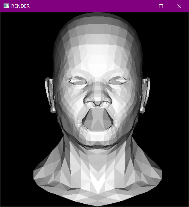
Lesson 3 Hidden faces removal (z buffer)
Even simpler: let us lose a dimension. Y-buffer!
这一节,展示如何通过1D图像和Y-buffer来演示2D图像。
Back to 3D
triangle(screen_coords, float *zbuffer, image, TGAColor(intensity*255, intensity*255, intensity*255, 255));

[...]

void triangle(Vec3f *pts, float *zbuffer, TGAImage &image, TGAColor color) {
    Vec2f bboxmin( std::numeric_limits<float>::max(),  std::numeric_limits<float>::max());
    Vec2f bboxmax(-std::numeric_limits<float>::max(), -std::numeric_limits<float>::max());
    Vec2f clamp(image.get_width()-1, image.get_height()-1);
    for (int i=0; i<3; i++) {
        for (int j=0; j<2; j++) {
            bboxmin[j] = std::max(0.f,      std::min(bboxmin[j], pts[i][j]));
            bboxmax[j] = std::min(clamp[j], std::max(bboxmax[j], pts[i][j]));
        }
    }
    Vec3f P;
    for (P.x=bboxmin.x; P.x<=bboxmax.x; P.x++) {
        for (P.y=bboxmin.y; P.y<=bboxmax.y; P.y++) {
            Vec3f bc_screen  = barycentric(pts[0], pts[1], pts[2], P);
            if (bc_screen.x<0 || bc_screen.y<0 || bc_screen.z<0) continue;
            P.z = 0;
            for (int i=0; i<3; i++) P.z += pts[i][2]*bc_screen[i];
             //未隐藏的部分会覆盖隐藏的部分,但隐藏的部分不会覆盖未隐藏的部分,这也是与上一节不同的地方。
            if (zbuffer[int(P.x+P.y*width)]<P.z) {
                zbuffer[int(P.x+P.y*width)] = P.z;
                image.set(P.x, P.y, color);
            }
        }
    }
}
Diffuse texture
在.obj文件中有一行是以"vt u v”开始的,这是纹理坐标数组。"f x/x/x x/x/x x/x/x"中间的x是这个三角形的纹理坐标,将其插入三角形内,乘以纹理图像的宽度和高度,你会得到你需要放到渲染器中的颜色。
上面比较难懂,以画一个三角形为例,我再说明一下,
- 以vt开头的行,"vt u v 0” 这是纹理坐标数组,也就是纹理图中缩小的相应的点(u,v),我们读取后放到vex_t中
- 以f开头的行,例如 "f a1/b1/c1 a2/b2/c2 a3/b3/c3" a1,a2,a3时三角形三个顶点坐标的索引,设vex为顶点坐标数组,vex[a1]=[x,y,z] (x,y,z)就是三角形一个顶点的坐标,就是a1索引对应的坐标。
- b1,b2,b3就是三个顶点a1,a2,a3对应的三角形的纹理坐标索引,例如vex_t[b1]=[u,v],(u,v)就是a1对应的纹理坐标。
- 再画一个点时,根据这个点在三角形内的位置,获得一个相对于三个纹理坐标的,相对应的点的纹理坐标。具体方法是三个纹理坐标分别乘这个点相对于三角形的三个顶点的重心坐标,再求和就得到了这个纹理坐标(u,v),然后u乘以纹理图像的宽度,v乘以纹理图像的高度,即可获得该点在纹理图像中的坐标,通过纹理图像,也就获得了该点应该渲染的颜色。
这个是画好的效果
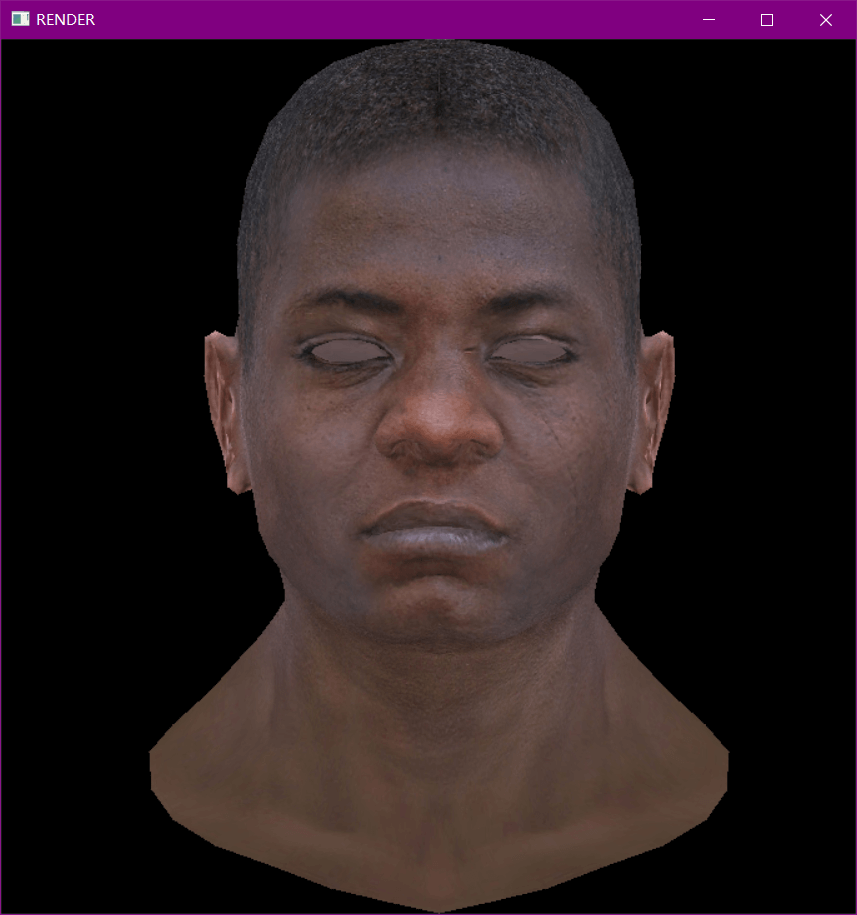
如果想要得到和教程中图片一样的,能够看到三角形边缘的效果,可以将得到的RGB颜色乘上之前计算得到的光照强度intensity。
Lesson 4 Perspective projection
首要要明白其次坐标系,之后就简单了。
先将3d坐标转化成其次坐标,然后左乘一个矩阵,这个矩阵就是投影作用,矩阵的值单位矩阵在第四行前三个值进行修改,分别对应x,y,z轴上的投影。
Lesson 5 Moving the camera
Chain of coordinate transformations
Vec3f v = model->vert(face[j]);
//viewport 映射到图像上,projection 投影 modelview 摄像机
pts[j] = m2v(viewport * projection * modelview * v2m(v));
- modelview 将模型中的坐标转化成像机坐标系中的坐标。如果我们想移动摄像头,我们可以移动所有的场景,让摄像头不动。
- projection 上节的投影
- viewport 模型坐标的值的范围是[-1,1],这样无法显示到屏幕上,通过这个变换,使模型能够贴合屏幕。
在将坐标矩阵重新转化回坐标点进行显示的时候要注意浮点的变化,也就是4舍5入,否则可能出现黑线或者黑块。
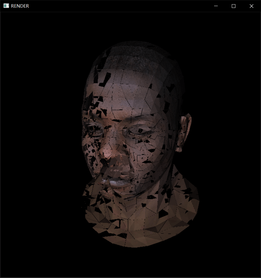
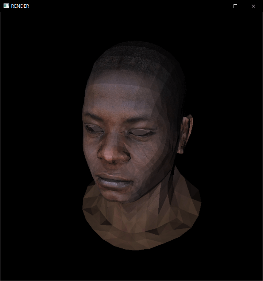
Lesson 6 Shaders for the software renderer
这一节首先整理了之前的代码,然后把着色器这一块拿出来进行修改。
最终的效果可以理解为几种纹理图像的叠加。